This is the second part of the Blimpduino presentation, the first one was a simple introduction and below you can read about the actual build. The procedure is pretty straight-forward with only a few tricky points and some need for improvisation. All the basic instructions are in the Blimpduino page on DIYdrones and you should read and check them before starting the assembly just to be sure you have everything needed and that you have a general view of how things should go.---
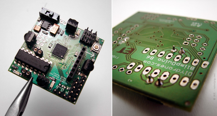
At first, every component is placed on the PCB. There is an option here. Instead of using the tall provided 7-slot pin that connects the ultrasound sensor to the board you can use male-female machined pins. The final assembly would be more compact and the sensor will fit more robustly. However I followed the instructions and use the provided tall pins. I started soldering the components by following the order dictated from the instructions and the soldering procedure I described in my previous post.
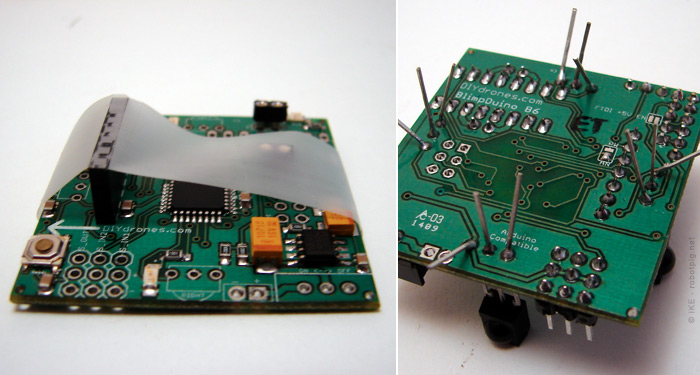
Some components require extra care like this piece of sticky tape that holds the pins in to place. Otherwise everything is problem free. The IR-sensors have long pins and can be soldered in whatever distance from the pcb you like. If they are right on the pcb's surface they are more robust but their view could be obstructed. Depending on the final components arrangement you can decide where you will solder them. I went for a medium height.
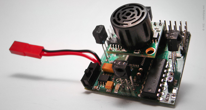
And this is the final board with all the components. I also soldered pins in some unused holes in case they will be at use in the future. The ultrasound sensor doesn't have a very tight fit, it stays in its place but has a little play. It can be easily removed if necessary (ex in R/C conrolled mode).
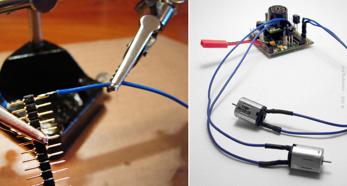
Here is the first tricky part. In order to connect the motors to the board the kit has -just enough- ultra thin AWG30 wire. I was afraid that after cutting some length to expose the wire from the insulation it it won't be enough so I used instead a conventional more thick wire. I measured it with a multimeter and it has similar resistance so from an electric point of view there is no problem. What I didn't knew is that the very thin wire can be connected to the pin via a special small tool without the need of soldering. That explains its use because I had a tough time soldering the wire to the pin as it is very easy to melt its plastic base from the heat. My solution was to quickly solder the wire to the pin stripe and after it was soldered to cut the two pins, thus using all the pin stripe as a heat sink. You really however should use the AWG30 tool and avoid all this trouble. I will order one soon.
A small remark: Although AWG30 wire is not something really exotic I have a hard time finding it in stores in Athens (Greece). Even with a sample they looked at it like a piece from an alien spacecraft so I just ordered it from Sparkfun, although I had already finished my Blimpduino.
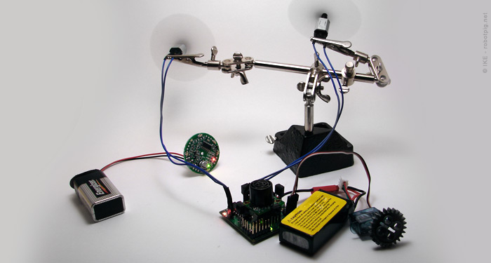
It's alive! With the props attached to the motors (just push them a little) and a very easy soldering of the 9V battery to the IR beacon the 3rd hand can be used as a test rig. The code was loaded with the FTDI cable. I used the code exactly as I downloaded it from the Blimpduino website, no modifications whatsoever. Everything seems to work ok. In this primitive test rig it is difficult to evaluate the performance but the basic functions are obvious.
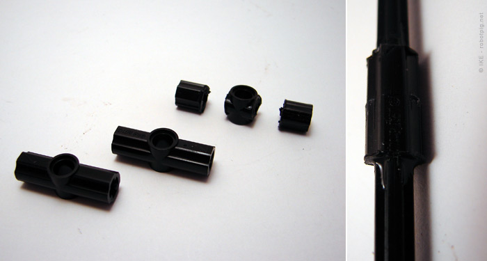
Another tricky point was a parts problem with my kit (one of the very first ones). There were 3 identical Lego parts instead of two with a hole and a simple cylindrical connector. I cut one of them in three pieces with the use of a lighter and a box cutter. The cuts may need a little trim. However I glued them (with CA glue) from the outer surface with the original finish and the fit was perfect. Some extra glue with the two small shafts and the final assembly is very robust and tough.
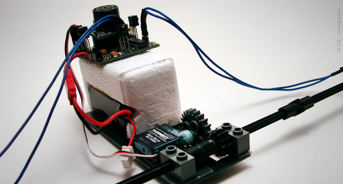
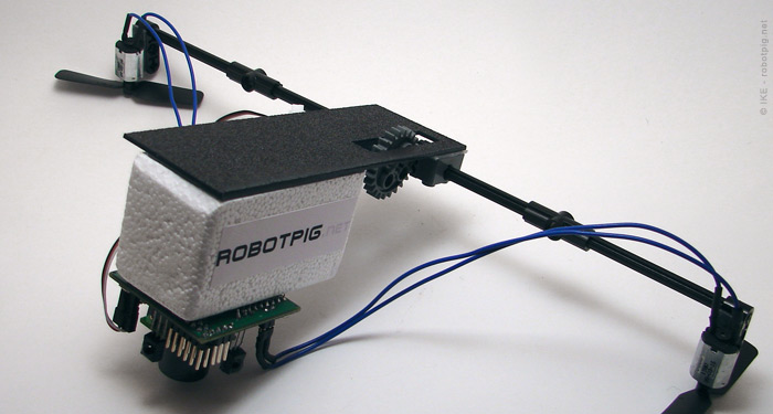
The final assembly. I used double sticky tape (much more forgiving than glue) to connect the Lego parts to the plastic plate. The servo is also held with double sticky tape.
My kit was one of the first and I bought the battery separately. Two extra Lego bricks are provided in the kit but I wanted something better (and better looking!). I used some foam I have stored from packaging (a new fridge has provided huge amounts) and carved a small box for the battery where it fits without any play. The pcb is on top, also with double sticky tape. The battery can easily be removed and its slot is slightly smaller so it fits tight enough in order not to move or fall.
I think it looks cooler than the OEM solution (OEM term is slightly overrated here)! You can see the other side in the first image of this post.
The only thing now missing is the envelope and of course the first flight, more on my next post.
Blimpduino - part 1